- #Create sequence diagram for free#
- #Create sequence diagram how to#
- #Create sequence diagram software#
Most of the specific features and restrictions of sequence diagrams compared to other diagrams derive from this strong guarantee that at all time, the graphical (vertical) order of the elements you see on the diagram match exactly the semantic order of the events which exist in the underlying model and the horizontal order of the instance roles you see on the diagram match exactly the semantic order of the corresponding elements which exist in the underlying model.įrom the specifier point of view, this means that sequence diagrams can only be defined on meta-models in which you can provide a total ordering of the events represented, and that you can reorder these elements in a predictable way (see the description of the Keeping the example above, moving executionĮ1 will trigger changes in the semantic model to move the corresponding event of

This is very different from what happens in other diagrams, where most graphical repositioning of elements are only cosmetic. Moving elements on a sequence diagram may trigger changes in the underlying semantic model to reflect the new event order implied by the positions you changed.

The most important consequence of this is that contrary to what happens on a classical diagram,
#Create sequence diagram software#
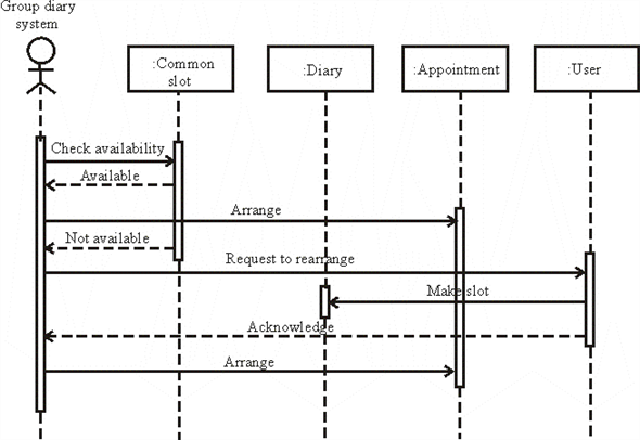
The canonical case is a UML Sequence Diagram (where the notation comes from), which represents the messages exchanged between objects in a software system. Typically, they representĮvents sent and received between some entities over
#Create sequence diagram for free#
Obeo UML Behavioral viewpoint (available for free at ) which is based on the Eclipse Foundation’s UML2 meta-model.Īs their name says, sequence diagrams are meant to represent ordered sequences of elements. The resulting diagram is available in the the specification of a UML sequence diagram editor. This tutorial is based on an example, i.e. It has been written for software architects who want to specify sequence diagrams on their own meta-models.
#Create sequence diagram how to#
This document describes how to specify sequence diagram modelers with Sirius. Sequence Diagrams Specifying Sequence Diagram Editors Place the condition for exiting the loop at the bottom left corner in square brackets. When that object's lifeline ends, you can place an X at the end of its lifeline to denote a destruction occurrence.Ī repetition or loop within a sequence diagram is depicted as a rectangle. Objects can be terminated early using an arrow labeled ">" that points to an X. Lifelines are vertical dashed lines that indicate the object's presence over time. Asynchronous messages are sent from an object that will not wait for a response from the receiver before continuing its tasks. Use half-arrowed lines to represent asynchronous messages. Messages are arrows that represent communication between objects. When an object is busy executing a process or waiting for a reply message, use a thin gray rectangle placed vertically on its lifeline.

Use the UML object symbol to illustrate class roles, but don't list object attributes.Īctivation boxes represent the time an object needs to complete a task. Class roles describe the way an object will behave in context.


 0 kommentar(er)
